Other 70s Planes
BRIERLEY'S COMPETITION
In February 1971, Mr Frank Brierley offered a prize of £5 worth of groceries per month for life to the first person to cross from the roof of his Peterborough supermarket to the other bank of the river Nene. This amounts to traversing 140 ft (42.7 m) to a grass bank 20 ft (6.1m) lower than the roof, from a standing start. A road bridge is conveniently situated for spectators.
The rules include "No gliding allowed", yet all entrants so far have made the first test of their wings on the actual course, presumably relying on the 20 ft height of the launch point, and only hoping to make forward progress if also descending, just as gliders.
The fact that all entries so far have been clearly underwinged is no bar to a serious entry. To be successful, it would appear that this course would need a very special configuration.
BIRDMEN
There have been several competitions and events, comparable to Brierley`s usually organised by persons of no aeronautical background. The aim is more for publicity rather than to achieve flight. One such event was reported as " - having proved once again that man powered flight is not possible. ". ( One of the purposes of this book is to show that it is. ) Some authors, understandably, don`t deign to mention them, but I do because there is always the possibility that the event can be transformed by making serious entries, as has happened with the Japanese International Bird Man Rally. Another approach is to consider them as a separate type of activity from human powered flight, with their own different validity, and it is undeniable that people do have fun watching the Bognor Rally and the Red Bull events. But do they fly ?
WRIGHT
Of the three HPA to fly in the spring of 1972, the Wright was the only one which was not the result of a take-over.
It was the first successful British one-person project. Peter Wright had trained on carbon fibre fabrication at Rolls-Royce, and was an active glider-pilot.
Wright started to design for quick construction in October 1969. A figure of 500 hours construction time is quoted for this aircraft.
He got clean away from glider or model-aircraft structures and pioneered the use of carbon-fibre on HPAs, using this material to reinforce EPS and PVC rigid foams, and also for diagonal taping. Pilot-support and transmission frame were welded mild steel tube. The transport joints were arranged so that the transmission could be tested inside the available workspace.
The Wright had the largest wing area yet of 486 sq ft (45.2 m2) and an empty weight of 95 lb (43 Kg). Flights were done with fixed elevator, the tricycle undercarriage being set to give take-off incidence. This was done to reduce pilot workload. There was only the rudder to think about apart from pedalling. Take-off was found to be easy, and flights of up to 300 yards (275 m) were made.
Initially the CG was too far aft. Another problem was that in flight the vertical chain jumped off the top sprocket - as on its contemporary, Jupiter. The transmission was, in principle, similar on both planes, although the proportionate length of chain-runs very different. The Wright propeller was 3-bladed and behind the tail.
In 1973 extensions on the wing-tips of the Wright increased the span to 85 ft (25.9 m) and the area to 521 sq.ft (48.4 m2).It was proposed to move the propeller to a nose mounted pylon, and to fit a 10 ft (3 m)propeller.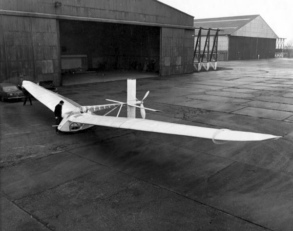
Peter Wright examining his aircraft in 1972. RAeS collection
MICRON
Wright's second aeroplane. By contrast, this had a wing area of only 134 sq ft (12.5 m2)on a 76 ft (23.2 m2) span. Material was glass fibre reinforcing a variety of foams, PVC, polyurethane and polystyrene. Construction took 200 hours up to February 1976. It was finished, then converted to a single-seat high performance sailplane which it continued to be for several years with the Buckminster Gliding Club.
TOUCAN
Martyn Pressnell, who had previous experience in the aircraft industry, with the Southend Mayfly group, and with aeromodelling writes:-
" By 1965 it was apparent that the current single seat machines would not be able to achieve the performance necessary for the figure of eight course. Consequently in September of that year four employees of the Handley Page Aircraft Company at Radlett in Hertfordshire founded the `Hertfordshire Pedal Aeronauts', under the leadership of their chairman Martyn Pressnell. Their object was to investigate the problems of man powered flight, and to obtain the support of the Company and the RAeS, to enable the group to build a second generation man powered aircraft.
"The early work of the group was concerned with a technical evaluation, and it soon became apparent that they could not expect to achieve a significant improvement by designing another single seater of the current type. The decision was taken in the true Handley Page spirit, to design a large machine powered by two men, which was to prove to be the biggest man powered aircraft constructed and flown in pursuit of the then current Kremer prizes.
"Initially the design studied had a wing span of 100 feet (30.5 m), but before construction began this was increased to 123 feet (37.5m) , In its later modified version the wing span became 139 feet (42.4 m), or about the same as a Boeing 707 airliner. In December 1966 a technical summary of the proposals was submitted to the RAeS, and this was enthusiastically received by the Man Powered Flight Committee then under the chairmanship of the late Mr. Robert Graham CBE.FIMechE.FRAeS.
"The size of the group had been steadily increased up to twenty, and with financial assistance assured in addition to members regular subscriptions, construction work commenced in April 1967. The total construction effort for the aircraft alone amounted to more than 20,000 man-hours, and as an entirely voluntary spare time occupation, this phase of the work spread over five years to 1972. The major problems, apart from the innovation and development of construction techniques, were concerned with the organisation of manpower and materials. Many members were doing this type of work for the first time, and many mistakes were made and corrected in the course of achieving the high quality of workmanship necessary for success.
"Initially construction took place in a private garage, but in order to make the big assemblies it was essential to have a larger workspace. Thus in 1969 work on the aircraft almost came to a halt while members built and equipped their own workshop on the Handley Page airfield at Radlett. This was originally two prefabricated bungalows some twenty years old. When erected and redecorated these provided an excellent, light and airy workshop measuring 66 feet by 21 feet (20 m by 6.4 m). A 250 yard (230 m) trench was dug in order to bring in power, and a large lathe was acquired from the Company.
"In February 1970 the Handley Page company went into liquidation after sixty years as an aircraft constructor. Many of the members of the group left the area, and for a time the future of the project was in jeopardy. However through the kind co-operation of the receiver, Kenneth Cork, Gully and Co., and Wingate Investments Ltd., the group were permitted access to the workshop and subsequently to have the use of part of a hangar, and latterly the use of the airfield for flight trials. The group were also indebted to Messrs. Humbrol for the gift of adhesives, I.C.I. for the gift of Melinex covering film and others for the provision of materials on favourable terms. The group were also indebted to Eastern Electricity for their assistance in solving the power supply problem after 1970. The group were rewarded in some measure, when on 23rd December 1972 Toucan I made the world's first flight of a two seat man powered aircraft, covering a distance of 68 yards. The weather conditions at the time were cold, overcast and flat calm. The pilot who had received a little gliding experience previously, was Bryan Bowen and the crewman was Derek May."
"A variety of mechanical, structural and other development problems remained to be solved. Following modifications to the wing incidence, dihedral and power transmission system, Toucan I was ready to resume flying on the evening of 3 July 1973. There was a slight headwind of about 3 ft/sec (0.9 m/s) angled 15 degrees across the runway at Radlett. Toucan I took off and climbed to about 18 feet (5.5 m) altitude, and flew in a stable and well controlled manner. It landed safely on the runway after covering a measured distance of 700 yards (640 m), and was airborne for approximately one minute and twenty seconds. A second flight was made of 340 yards (311 m), both flights terminating because of lack of oxygen in the cockpit and the high airborne pedalling rate, which exhausted the crew.
"Serious damage occurred to the starboard wing in an accident, and for the remainder of 1973 and most of 1974 the aircraft was undergoing repairs. The opportunity was taken to increase the wingspan by introducing a central 16 feet (4.88 m) extension, as well as rectifying the other defects mentioned. On completion the machine was renamed Toucan II, and flight testing continued until September 1978. Several dozen flights were achieved ranging up to 500 yards (457 m), and throughout its long career it proved to be a stable and controllable aircraft in straight flight. Although it could be controlled adequately in a cross wind up to 3 ft/sec notwithstanding its slow lateral response, turns were not attempted because of the potential risks involved in landing off the paved runway. The wing was badly damaged on two further occasions because of inadequacy in the strength and impact absorption of the outrigger wheels. This problem was cured by the introduction of flexible plastic tube outriggers, and in 1978 taxying on grass was inadvertently accomplished without mishap.
"It became necessary for the Hertfordshire Pedal Aeronauts to leave Radlett airfield because of redevelopment in October 1978. Realising the difficulty of rehousing the project at another airfield and with due regard to the age of the aircraft, the decision was taken to present Toucan II to the Shuttleworth Collection where it was for a time handsomely exhibited alongside its forebear SUMPAC. The library at Old Warden was handed a set of working drawings and technical data referring to the project.
"It is doubtful if the full potential of the two seat machine has been realised by this single successful project. The anticipated advantages include better power to weight ratio, improved power continuity particularly when the pilot is engrossed in flying, and improved aerodynamic ground effect associated with the high span. These advantages were evident on Toucan on certain occasions. However the sheer size of the two seater and the relative fragility of the wings presented numerous problems. The group considered that this, allied to the elusive proper combination of calm weather, aircraft serviceability, and human willpower, made for protracted progress."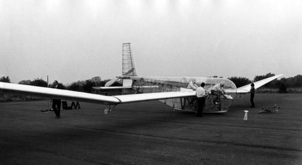
Toucan at Radlett airfield. RAeS collection
“Toucan II is a fixed wing monoplane of 139 ft (42.4 m) span, 29 ft (8.8 m) in overall length and 13.5 ft (4.1 m) in height. It was powered by two men sitting in tandem in conventional cycling attitudes, with the crewman in front and the pilot behind. Both men pedalled on cranks which transmitted the effort through light alloy chains to the main wheel for ground propulsion. When airborne the power was transmitted through a torque shaft in the rear fuselage to a 10 ft (3 m) diameter propeller mounted behind the tail. The empty weight of the aircraft is 241 lb (109.3 Kg), and with the crew onboard it weighed 550lb (250 Kg). The wing area is 696 sq.ft (64.7 m2) and its aspect ratio is 27.8. The flying speed was 18 to 20 mph."
Wing section selected was NACA 633618, similar to that used on several previous machines but with the centre of pressure and the greatest depth further forward. It was not expected that extensive laminar flow would be achieved, and Martyn said (1989), "Maybe we would have done better with a turbulent flow section". Wing primary structure was a spruce spar, torsion being carried by a lattice box of spruce strip. The fuselage frame was conventional aircraft riveted light-alloy sheet, of 30 gauge (0.315 mm). This proved light and satisfactorily supported both crew. For the first time in Britain, foam plastic sheet was the main skinning material (see Linnet).
Pressnell continues:- "Materials used in the construction included large quantities of Balsa wood and expanded polystyrene, [ this would have been the white 1 lb/ft² foam, the only available at this time. ] as well as spruce mainspars and longerons, thin aluminium alloy sheet, titanium, and nylon cord. Melinex, a transparent plastic film, was used to cover the airframe and was shrunk drum tight by being warmed. Accurate construction depended on the use of flat surfaces, as with model aeroplanes. The tools employed included razor blades, pins and pegs as well as the more usual wood and metalworking tools.
"Airborne control of the aircraft was achieved by an all moving tailplane and by slot lip ailerons set in the outer wings. These ailerons provided co-ordinated roll and yaw, and at extreme deflection provided a strong yawing effect obviating the need for a conventional rudder
"It was appreciated by the group that the wake of a rudder, when deflected would have interfered with the tail-mounted propeller.
"A single main wheel of 16 inches (406 mm) diameter, fitted with a (2 inch 50 mm) balloon tyre absorbed normal landing impacts. The nose wheel permitted the machine to take up a nose-down ground attitude. Thus the wing produced little lift during taxying, which improved traction through the main wheel and enabled the aircraft to be accelerated above flying speed on the ground. On raising the nose the machine was able to zoom to a modest altitude. This ground angle also assisted braking the aircraft on landing, which was achieved with two bicycle brakes, one on each wheel. In flight the wing tips deflected upwards about 8 feet which together with the built-in dihedral angle, ensured that the tips were not close to the ground. At take off the wing tips were steadied by running handlers, and on landing small outrigger wheels were provided under each wing to stabilise the aircraft.
"The group was organised on broadly democratic lines, with elected executive officers guided by two committees to consider design and administrative matters. The committees operated within a framework of agreed rules, which fixed their constitution and member's rights and responsibilities. It was a non profit making private organisation with a membership fee set at £ 0.50.
"The group was founded in 1965 by Martyn Pressnell, Reginald Lambert, Christopher Dudfield and Gordon McGregor, all colleagues in the technical departments of the Handley Page aircraft company. Their colleagues in the company, their families and friends, actively encouraged the enterprise. In addition to completing the initial technical evaluation, the founders expanded the group and guided it in the early construction and organisational phases. The membership was drawn from inside and outside the company, and embraced a diversity of practical, technical and professional skills.
"The pilot Bryan Bowen and the crewman Derek May were not practicing athletes, but kept fit by cycling frequently. The pilot learned to glide ab initio with the London Gliding Club at Dunstable as a preliminary to flying the man powered aircraft, and experienced no difficulty in coming to terms with it.
"The enthusiasm for the project was found to be self generating when it was under way, most members regarding the pursuit as a challenging hobby. The Kremer Prizes, while giving strong initial impetus and a long term goal, were thus found to be augmented by this more immediate reward. "Group Officers, "M.S.Pressnell BSc. CEng. FRAeS. (Chairman) "P.R.Sladden BSc. (Vice Chairman) "P.L.Jones BSc. CEng. MRAeS. (Secretary) "R.E.Harris BSc. (Treasurer) ".
On Toucan a vane-operated air-speed-indicator was fitted. The pilot would see one of three coloured lights according to the airspeed.
Martyn Pressnell later became Vice-Chairman of the RAeSMPAG.
See Table of Types for details of this and other aircraft.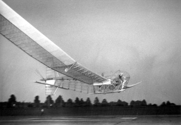
Toucan flying at Radlett. RAeS collection
NIHON UNIVERSITY (continued)
At Nihon University progress continued, as described by Prof. Kimura :- "In 1972, a well equipped runway, 620 meters in length and 30 meters in width was completed along with a hangar in the precincts [of Nihon University]. The research base for HPA was moved out there. At the same time, model changes were carried out. The new series was named the `Egret', which was supposed to fly better than the `Linnet'.
EGRET
Prof. Kimura continues :- "The major changes incorporated in the Egret series featured the introduction of a belt drive to shorten the power transmission system. This was made possible by putting up a pylon for the propeller right behind the cockpit, as seen in the SUMPAC and Jupiter." ( Kimura 1977 ).
(See Mufli for discussion of length of transmission.)
Three Egrets were built, still following the pattern of one HPA per year from Nihon University. For details see Table.
Kimura continues "The 1975 student team was composed wholly of enthuthiasts who had been helping their seniors with the manufacture of HPA since their freshman days. The team had as its leader an expert designer named Junji Ishii. I decided that I could entrust them with the task of undertaking drastic model changes. We confidently crowned the new model with the name of the "Stork" which is something of a flier."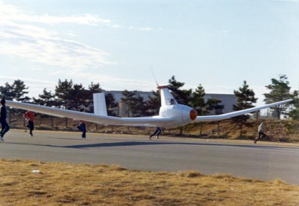
Egret A flying in 1975. RAeS collection
STORK
The distance flown by Stork was ten times anything previously flown at Nihon, and almost twice the distance of its predecessor Jupiter, which it closely resembled.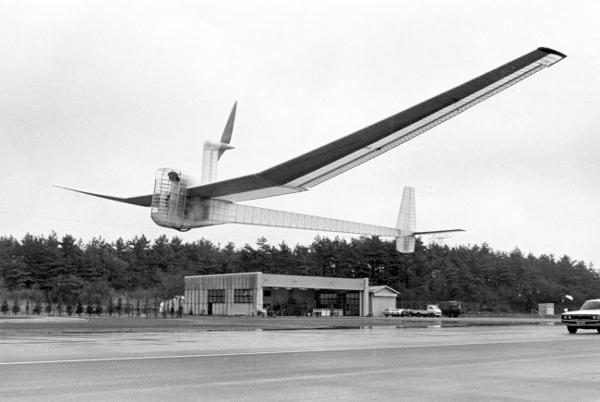
Stork flying in 1976. RAeS collection
STORK'S IMPROVEMENTS ON JUPITER
The control bar support is arranged to make it much easier for the pilot to get in or out, and this arrangement on the Stork probably made rigging easier. On Jupiter the control bar is supported sideways from the nose of the wing. This meant that the fuselage on its own could never be rigged for testing the transmission; the centre section of the wing needed to be there as well.
Since on Jupiter none of the Balsa plywood actually forms the profile, the Melinex being held away from the wood by the sponge, there is no reason for the Balsa-plywood-torque-box to be any special shape. A logical developmental step is to simplify and lighten, and to make this a square box as was done on the Stork, which led to a more structurally efficient wing.
The elevator is positioned behind the fin on the Stork. As well as making the elevator more effective, having a longer moment-arm, it again simplifies and lightens. This component is in one piece.
RIGGING
The author is reminded that there are rigging implications here too. It is important to have a pre-thought-out system for the order in which the components are assembled. It must be borne in mind that the machine when half-rigged will not balance. On at least one occasion with Jupiter, during rigging, the fuselage tipped over because of the uneven weight at that stage. When it was a wing-tip that it "landed" on, then it only needed picking up. When it was the elevator tip, then this component was damaged. With the Stork's improved layout, the elevator can more easily be attached last and detached first.
Other improvements, apart from those details to be expected in any series development, are the castoring tail-wheel and a proper ventilation system. With less power required, the pilot was able to think about turning, and flights involving turns were at least comparable with the best turning performance shown by Puffin II.
On 2nd January 1977, Stork was officially observed to fly 2,290 yards (2,094 m), exceeding Jupiter's 1,171 yards (1,070 m), and thereby becoming the holder of the World Distance Record.
IBIS
Nihon's 1978 aeroplane, followed the same general configuration except that the wing was mounted lower. Ibis was a slightly smaller plane, and its performance less.(Continue to Milan)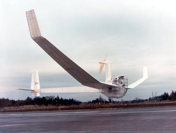
Ibis A. RAeS collection
DRAGONFLY
Roger Hardy, who had flown Jupiter, designed and built two versions of his Dragonfly in Prestwick, Scotland.
Hardy's approach was to make his only innovation the fact that there were no innovations. The Dragonfly was the sort of neat looking plane you feel you want to make a model of. It had a smaller wing-area than its predecessors and used the Wortmann aerofoil section FX63137. There was a side-door for the pilot, unusual at the time. Ailerons moved up only.
The Dragonfly made some short flights in early 1975, but Hardy went onto his second version in the February. It was estimated that the plane would fly at 28 ft/sec (8.5 m/s) with a lift coefficient of 1.15 and a pedal cadence of 70 rpm. He recorded his hours spent on this one-person venture. Design took 1,000 hours and construction 1,610 hours, being comprised of wing 740, aileron 60, fuselage 200, tailplane 40, fin 80, pylon and propeller 80, covering 180, mechanism 160 and final assembly 70 hours. This was all within a period of 22 weeks. No drawings were made. Roll-out was on 30th July 1975.
Problems then arose. The spar buckled, resulting in two weeks of repair work, and the propeller flexed, hitting the pylon. There was damage to the rear-fuselage from ground-handling. The cg intended as 38% m.a.c was found to be at 25% m.a.c. This necessitated 4 lb of ballast in the tail. In February 1976 he had notice to quit the hangar, the aircraft not having flown by this time, for lack of elevator power.
LONGITUDINAL TRIM
Flying characteristics are affected by the position of the centre of gravity (cg) relative to the wing, just as take-off and landing are affected by this position relative to the wing and to the wheel(s). Which part of the wing? The mean aerodynamic chord (m.a.c.) is the convenient reference against which to quantify trim. It is the "average" chord-line, defined by a formula which recognises the fact that those parts of the wing with greater chord have a greater effect on pitching moment per unit area; (m.a.c.)squared x span = integral of (chord)squared along span.
AVIETTE
The word "aviette" is literally French for "small aeroplane", and usually refers to the class of flying bicycles of the twenties which typically had ground-drive only. By contrast, Monsieur Hurel's 1976 aircraft had an 137 feet (42 m) span and a 12 feet (3.7 m) diameter propeller.
On the Aviette, Hurel used an aerodynamic solution to a structural problem. As explained above (see Lippisch), it is important that the wings of aircraft do not warp or twist uncontrollably. The obvious answer to this is either to stiffen the internal structure to resist torsion, or to arrange external bracing wires to do the same job. However, on this plane stabilising surfaces were attached on mini-tail-booms behind each outer wing. Just as the effect of a tailplane is to tend to return the entire aircraft to a level attitude from a non-level attitude, so the effect of these surfaces is to tend to hold the wing-tips at a constant angle relative to the airflow. The conventional constructional techniques of the time were used, materials being spruce, Balsa and Melinex.
The Aviette flew at Le Bourget, largely through national recognition of the designer's contribution to industry throughout his working life.
In 1974 the Aviette recorded flights of 1100 yards (1000 m).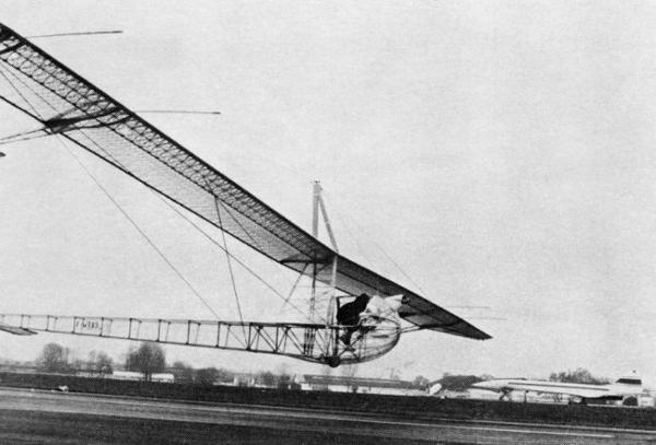
Hurel Aviette flying at Le Borget airport
BURD
The Biplane Ultralight Research Device, was the first attempt at HPF by students at the Massachusetts Institute of Technology, Cambridge, MA, USA (MIT). They chose the configuration of a two-seater canard biplane, with the propeller mounted behind the fin. Span was 63 ft (19.2m) with a total wing area of 640 sq ft (59.5 m2) of FX61-163 section. Spoilers were incorporated for lateral control. Spar was laminated Balsa. Considerable structural analysis of many of the primary and secondary components of the BURD was performed by Paul Hooper and Robert Peterson. However the capability of the wing to resist being bent forward was neglected, with the result that the wings of this promising two-seat biplane collapsed forward during rotation on its first flight-attempt in 1972.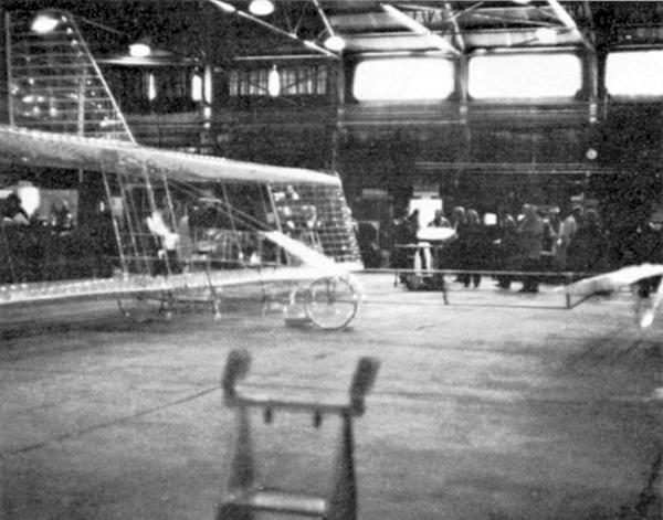
MIT BURD. RAeS collection
WING RIBS
The students had been very concerned with details, particularly the wing-ribs, but neglected the fact that the main loading on these derives from the tension of the wing-covering when it is shrunk taut, rather than the theoretically calculable air pressure loads applied during flight, and hence these secondary components can only be tested by a full-scale wing-test-section as mentioned above. Ribs on BURD were, as was usual at the time, of Balsa-strip girder construction. It has been said that there is no such thing as a perfect rib, and that there are lots of ways to make ribs. Questions to ask when choosing a method of rib construction are :-
How long are they going to take to make ? (there are a lot of them)
How long are they going to take to line-up and fix to the spar and trailing edge ?
Are they going to be easy to fix the covering to ? (particularly if there is reverse camber)
Is the rib-cap (the strip of material which follows the curve of the profile) going to remain attached to the rest of the rib ? (particularly awkward if carbon caps are on foam ribs.)
Will they resist the effect of the Melinex, if used, being shruck taut ? (unlike flight-loads, this load is applied even when the plane is stored)
and, lastly, are they light enough, strong enough and the right shape?
The BURD II was built between 1974 and 1976 to the same shape but from different materials. The wing-spars were foam and graphite-epoxy, which resulted in the weight being 112 lb (50.8 Kg) compared with the 130 (59 Kg) of the Mk 1. However this plane could not be made to fly, even when, years later different students dusted it off and added model-aeroplane engines. This attempt however, led to the successful Chrysalis (below), which in turn led to other aircraft from the same academy. Perhaps the main lesson to be learned from the BURD project is to not be deterred by lack of early success.
OLYMPIAN ZB 1
This was a one-man venture by Joe Zinno, an ex-pilot. The first HPA to fly in the continent of North America, the Olympian ZB 1 made its first flight on 21st April 1976. Reay observes that there many similarities between this aircraft and Jupiter (Reay 1977). There are also many differences :-
|
|
Olympian ZB1 |
|
|---|---|---|
|
Aerofoil |
Wortmann |
NACA |
|
Continent of origin of aerofoil |
Europe |
N.America |
|
Lateral control |
Rudder only |
Conventional |
|
Fuselage |
Pod and Boom |
Glider-type |
|
Length |
18ft |
30ft |
|
pedal-type |
treadle |
rotational |
|
Rudder-control |
One-hand |
Both-hands |
|
Wing-position |
Mid-wing |
High-wing |
|
Wing-nose Material |
E.P.S. |
Balsa |
|
Success in completion by originator |
Yes |
No |
ICARUS
Taras Kiceniuk's Icarus aircraft was flying in the Mojave Desert of Southern California in the same year that the MacCready team were using this space to fly their Gossamer Condor; at one time the two planes shared a hangar. As on the Condor, materials were light alloy tube, foam and Mylar.
The propeller on the Icarus was concentric around the tail-boom; it was the first time that an aircraft with this scheme had been completed. Taras Kiceniuk, who helped with the Gossamer Albatross, was later part of the prize-winning Bionic Bat team, which adopted a similar propeller position. The author started to construct an aeroplane with such a layout (see above) and this system is used on the current Airglow. The weight per inch of the carbon-fibre 4 inch (101.4 mm) diameter propeller final drive shaft on Airglow is the same as that of Jupiter which was of light alloy and only 1 inch (25.4 mm) diameter. Such a scheme was considered for Daedalus, and then rejected.
Icarus had a very low wing; so low that on take-off it would have been influenced by the type of ground-effect which becomes significant when the height is a fraction of the chord. The Reluctant Phoenix appeared to benefit from this, but on Icarus, take off was only possible if the aircraft was towed (See Dumbo/Mercury and HVS ).
Fabrication technique of the wing was hot-wire cutting from solid blocks of foam, as used on LiverPuffin and later the Light Eagle and Daedalus.
BLIESNER SERIES
Wayne Bliesner has designed built and flown a bewildering number of HPA, producing about one new aircraft or new variant each year. This prolific enthuthiast has had the benefit of membership of the Flight Research Institute, Museum of Flight, Seattle, Washington State, USA. This institute has assisted various forms of flight research and aerodynamic research including the Alcor Program where a pressurised glider explores the waves in the lee of mountains; and a project which tested improvements in the drag-reduction of an Olympic 4-place Bobsled. Membership was open to all, but employment with the Boeing Company is required for use of some of the facilities of the institute.
Bliesner's first three aircraft only made flights under tow.
After the successful flight of the fourth, there followed a series of planes using the same elliptic spruce-spar wing. Various propeller positions and tail arrangements were tried during this time.
Airplane 8 was also known as Man-Eagle 1. It is at this point that Bliesner decided to aim for speed. He designed a new aerofoil, and built a new wing with a carbon spar. This wing was progressively trimmed, and the Man-Eagle variants had different spans as well as different fuselage arrangements. Stored-energy was used on Man-Eagle 3 (Bliesner 10). Man-Eagle 4 had a sophisticated shape pod and is comparable with Pelargos 3.
Bliesner 1 Wayne was a student at the University of Washington when in 1975 he built his first HPA. This was a flying-wing design. The wingspar was a girder of brazed aluminium tubes, the ribs Balsa. propeller was on a pylon above the pod. The plane was designed to fly at 12 mph, as indeed it did, but only when towed. Unfortunately before further flight tests could be made, a storm destroyed the temporary hangar and the aircraft with it.
Bliesner 2 Of the hardware, only the propeller was salvaged from the first plane. Of the design, the low-wing position was retained, as was the pylon-mounted propeller and the principle of a brazed-tube spar. This was a conventional layout with a recumbent pilot and glider-type rear-fuselage. This aircraft made flights in 1977, but again only under tow.
Bliesner 3 A new wing was built for the 1978 trials. This was of elliptic planform, spruce spar and foam ribs. The fuselage was designed around the possibility of a water-landing, with pilot access from the top, and a hopefully ditching-proof lower part. This plane made many tow-assisted flights, until it crashed after stalling at a height of 20 ft (6 m).
Bliesner 4 " The wing was rebuilt to its original shape and a new fuselage with better contoured surface was constructed. The wing was left low with the pilot sitting on the wooden spar. Drive train problems on the previous aircraft led to the decision to run the propeller on a short pylon at the front of the fuselage.
" A debate had occurred for several years as to whether it was better to put the propeller in front where it saw clean flow but the fuselage or pylon suffered from the propeller wash penalty or to put the propeller behind in the fuselage wake but with no resulting propeller wash penalty.
" The configuration was moved to Arlington airport where a hangar allowed partial assembly. A large unused runway was available for flight tests. This proved to be an ideal site for straight line flight. This aircraft became the first [of his] configurations to be pedalled off the ground without tow assistance, and several short flights of up to 100 yards (91 m)were achieved.
Bliesner 5 " News of the English Channel crossing [see Gossamer Albatross] and the fact that carbon fibre was now available led to the decision to make another design improvement"
(Flight Research Institute. Status Report 1987-8)
The 1980 fuselage which characterised the "5" incorporated a carbon structure, a new propeller and an upright seat. It had two wheels side-by-side in front so that unlike most HPA it was stable when standing on the runway. This made it easier for one person alone to manage it on the ground. Flight distance increases up to a mile were attributed mainly to the new propeller. There were many occasions when the aircraft was assembled, taxied out to the field and flown with only the pilot around. Bliesner had not expected that this could be done, but having discovered that it could, decided to retain this capability in later designs: but he did this later with single wheel aeroplanes.
The upright pilot position was considered to be the major cause of a nose-over, when the aircraft was blown into a ditch while taxying, and it was decided to revert to a recumbent pilot position for pilot safety. (Four years later the Monarch team suffered a similar crash while on the ground, and adopted a recumbent position for their new fuselage.)
Bliesner 6 First of the series with a high wing; this feature was retained thereafter. Pilot was recumbent, as mentioned. The propeller was in front, as before, but the lower fuselage necessitated a short pylon. This variant only made a few hops before the failure of a wing to fuselage joint which had been hastily put together led to the destruction of the fuselage.
Bliesner 7 This 1981 aircraft was the last to use the wooden wing. Three actions were taken to reduce interference drag: the propeller was moved up to be pylon-mounted: the fuselage-wing junction carefully faired: and a "V" tail built.
It was found that the tail-boom flexibility considerably reduced the effectiveness of the tail ( See later Light-Eagle, where this phenomenon is studied). Also, "the high thrust line required large pitch adjustments when the pilot power varied during flight". (This effect had concerned the author when designing Jupiter, which had a pylon-mounted propeller, but in flight on that machine it was found that any variations in pedalling rate led to changes in speed only, not in attitude. It was not a concern for the pilot of that aircraft).
Flight tests on this plane were terminated so that a new wing could be fitted. This new configuration, the Bliesner 8, which was named Man-Eagle is described later.
SUMMARY of BLIESNER AIRPLANES 3 to 7
In all cases the wing was 80 feet (24.4 m) span, 300 sq ft (27.9 m2) with spruce spar. Lateral control was conventional.
Unless specified, seat was recumbent, tail conventional on boom.
|
MK |
Year |
Special features |
Wing position |
Propeller position |
Flight results |
Reason for termination |
|---|---|---|---|---|---|---|
|
3 |
1978 |
Waterproof pod |
Low |
Short pilon |
Towed only |
Crashed |
|
4 |
1979 |
Better fared pod |
Low |
Short pilon |
100 yards |
Desire to improve |
|
5 |
1980 |
Upright seat Twin wheels New propeller |
Low |
Nose |
1 mile |
Crashed |
|
6 |
1980 |
|
High |
Short pilon |
Few hops |
Crashed |
|
7 |
1981 |
“V” tail |
High |
Long pylon |
Initial tests |
New wing ready |
PHILIPS
Two HPAs were designed and built by Ron Philips, a cycle enthusiast of Humberside, England in the mid 1970s. The Philips Mk I had a span of 80ft (24.4 m) and a weight of 190 lb(86 Kg). The Mk II, a two-seater, made some flights under tow.
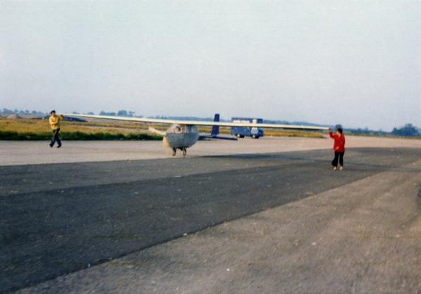
Philips MK II. RAeS collection
VERSTRAETE/MASSCHELIN Bros This Belgian trio made several elegant machines contemporary with the Aviette. One was transported to France to fly at Calais-Marck airport because the Belgian authorities would not grant a permit to fly. The flights were remarkable for the altitude gained (about 15 feet (4.5 m)) and the performance on a base adjacent to the sea where wind is both fierce and gusting. Wingspan was 85 feet (26 m) and weight 117 lb (53 Kg).
NEWBURY MANFLIER
In the mid 1970s, when the first few British aircraft had flown but failed to win the figure-eight prize, people were looking for new approaches. Rear Admiral H C N Goodhart CB, a champion glider pilot with other aeronautical experience, had the idea of increasing the span without increasing the weight of the wing, by distributing the load along its span. In 1975 he designed the Newbury Manflier with two pilots seventy feet apart, each in their own fuselage. When the author saw this machine under construction, it looked to him like two Jupiters tip-to-tip, the wing having a span of 138 feet (42 m), an area of 198 square feet (18.4 m2) and a Wortmann aerofoil section.
The control system was simply an elevator for each pilot. To yaw (right or left), one pilot pedals harder; to roll, one applies up-elevator; to pitch, both apply up-elevator. There were no ailerons, and both fins were fixed.
The structure was similar to the earlier British machines except that the wing spar was a plywood tube for torsional stiffness and shear, with spruce upper and lower booms. Drive was by chains to propellers on pylons, one for each pilot, who were in upright cyclist positions. This aeroplane had the widest undercarriage of any aircraft ever, and could only operate from a very wide runway.
The Newbury Manflier first flew in 1979 at Greenham Common, England which was available at the time. It demonstrated that a satisfactory command system was possible for this configuration. Surprisingly, what worked best was for each pilot to look after his own end. No captain, or "coach" on the ground, which were the other two options that Nick Goodhart had considered.
Other problems were however more significant. One of these was structural. For a simple cantilever wing, it has been found satisfactory to calculate the loads to be expected during cruise, and then by applying a constant factor along the span to make allowance for all contingencies such as gusts or manoeuvres. However the effect of localised gusts which affect only part of the wing cannot be allowed for in this simple way. HPA operating close to the ground, and having large wing spans are probably more susceptible to these localised gusts than other types of aircraft, and little is currently known about such gusts. A local gust will be more serious for a wire-braced wing or a wing of unconventional loading such as the Newbury Manflier than for a cantilever.
On this topic, though not specifically about the Newbury Manflier, John McIntyre writes, "Localised gusts are a big problem for HPA - this is probably what broke the Daedalus wing at Santorini. Prediction of deflection failure mode for a wing with a single bracing wire, such as Daedalus or Airglow, in gust/manouevring is difficult - the problem is non-linear, requiring iteration for an accurate solution".
In the author's opinion this could have affected the Newbury Manflier but Nick Goodhart disagrees.
Goodhart writes :-
"The aircraft, suffered a wing spar fracture due to bad construction and lack of fuselage torsional stiffness due to bad design. After repair the wing spar proved entirely satisfactory and took up exactly the predicted shape in flight indicating that the loadings were as anticipated. "The project was terminated soon after the first (two) flights had been achieved as the hangar and runway at Greenham Common became unavailable".
These flights immediately preceded the time when the base was more well-known for groups of women a few feet outside it than for a pair of blokes a few feet above it.
Nick Goodhart had once flown a two-seat glider with Paul MacCready the designer of :-
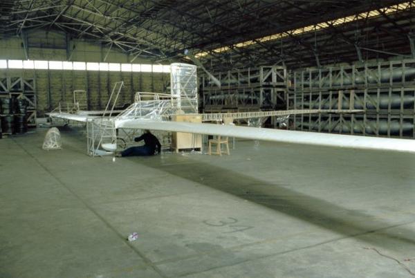
Newbury Manflier in it’s hangar at Greenham Common. RAeS collection
